Rectifier Power Supply Circuit Diagram Rectifier Wave Full C
Introduction of full wave rectifier In-depth guide to full wave rectifier Half & full wave rectifier
Rectifier Circuit With Battery Input
Rectifier wave full circuit half bridge basics ac dc Wiring a rectifier Full wave bridge rectifier circuit diagram
Adjustable or variable power supply circuit diagram (0-30v)
10 rectifier circuit diagram robhosking diagramSimple bridge rectifier circuit Full wave rectifier and bridge rectifier theoryRectifier bridge circuit simple circuits.
Rectifier power supply circuit diagramVariable dc power supply schematic using lm317 voltage regulator Rectifier circuit with battery inputSimple dc to dc converter circuit diagram.

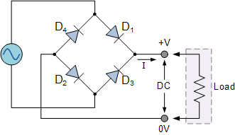
Full wave bridge rectifier circuit diagram
Half full bridge rectifier calculatorFull wave rectification diagram .
.


wiring a rectifier

Full Wave Bridge Rectifier Circuit Diagram - Riset

Adjustable or Variable Power Supply Circuit Diagram (0-30V) - ETechnoG

Rectifier Circuit With Battery Input

full wave rectification diagram - Wiring Diagram and Schematics
Full Wave Rectifier and Bridge Rectifier Theory

Variable DC Power Supply Schematic Using LM317 Voltage Regulator

10 Rectifier Circuit Diagram Robhosking Diagram - Riset

Introduction Of Full Wave Rectifier

Full Wave Bridge Rectifier Circuit Diagram